DIY Flat Pack LED Desk Lamp

Before getting in the shop, we sat down in Illustrator and designed a lamp made from wood and acrylic with LED's as the light source. Then we went through the set up process to get the x-carve ready to carve. We are first carving 1/2” plywood to make the lamp base, arm, and a wooden cap that will hide the LED’s.

In order to hide all the electronics, we are making two halves that mirror each other and carving out where all the wires, switch, and adaptor will be. That way we can place the electronics in one side and cover them up with the other, making them hidden.
For all wood pieces we used an 1/8” straight bit for all the carving on the x-carve. First, we carved out the base which turned out perfectly.
Once the first sheet was done, we put on a new 1/2” sheet and carved the pieces where the arm will connect to the base, the pieces for the acrylic, and the arm. We left a link to this Easel file down in the description below if you want to make this lamp yourself, or try out Easel for the first time. It's a free online software and has so much creativity. You can even import your SVG files straight into this program like we did and it works out perfectly.

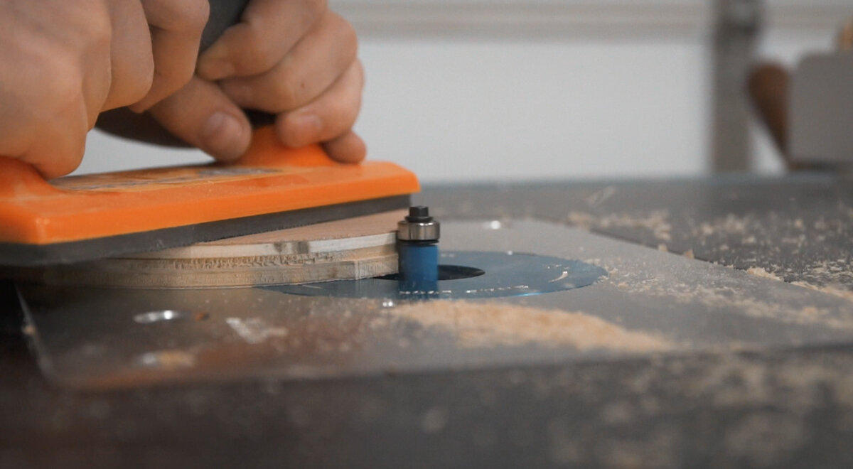
Instead of cutting the pieces all the way through with the CNC, we decided to only cut half way through to save some time. Then we cut them completely out with the band saw. Then we can use a flush trip router bit to clean everything up

Now over on the router table, we first used a flush trim bit to to take away the extra bits we left when we cut the pieces out on the band saw.
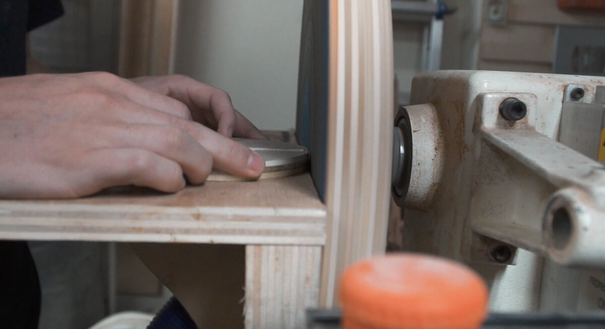
Next we used an oscillating belt sander and the disk sander to sand down and make the edges nice and smooth. On the base pieces we sanded a small section flat where the switch will stick out so it'll sit nicely and not want to roll around the rounded side.
Now to make the holes for said switch. We used a half inch forstner bit and drilled through both pieces like how they would be when all done. To keep them from moving around, we put them in a vice and that worked really well.

We can finally move onto something we are so excited for. We have never carved acrylic on the x-carve before and we are so interested to see how it turns out. Again using the same 1/8” straight bit to do the roughing pass, which it just the outline. Then we switched over to a 60 degree v bit for the detailed pass. This pass is going to do magic, not only is it bringing our idea to life, but we can start seeing how 3d the design will be.

We are going to do the same process as with the wood and roughly cut out the acrylic with the bandsaw and then move over to the router table to flush trim it up.
And now one of the most satisfying things ever. Peeling back all the paper…

We wanted to make the edge of the acrylic where the lights will be coming though a little clearer so we used a torch to melt away the plastic so to speak just by going back and forth with the flame diligently. this method seemed to work out pretty well I would say.

Always do a dry fit always first before gluing up, just to be on the safe side. Then we could glue up all the pieces that needed to be paired together.

This is the cap for the acrylic (below) after the glue dried, and here you can where the LED’s will lay flat inside the groove, and where the wire will come out the top and run to the base to connect to the switch and power.

After a quick sanding of 120-220 on everything, Paul convinced us to do a 1/16” round over on all the pieces. We were a little hesitant at first, because we didn’t think it would make a huge difference, but it actually did and we are now converted. Doing this on every project from now on.

Finally time for finish. we wanted to keep the wood as natural looking as possible, so we used lacquer and did two coats on each side and all the edges.
After that dried, we can assemble everything for the first time. The piece that attaches the arm to the base is just screwed on from the bottom. The arm was attached with 1/4 20 x 1 1/4” bolts (affiliate link) and a wing nut (affiliate link) so the arm can adjust to different angles. The top is attached the same way with the same size hardware.
Now it's time for wiring.
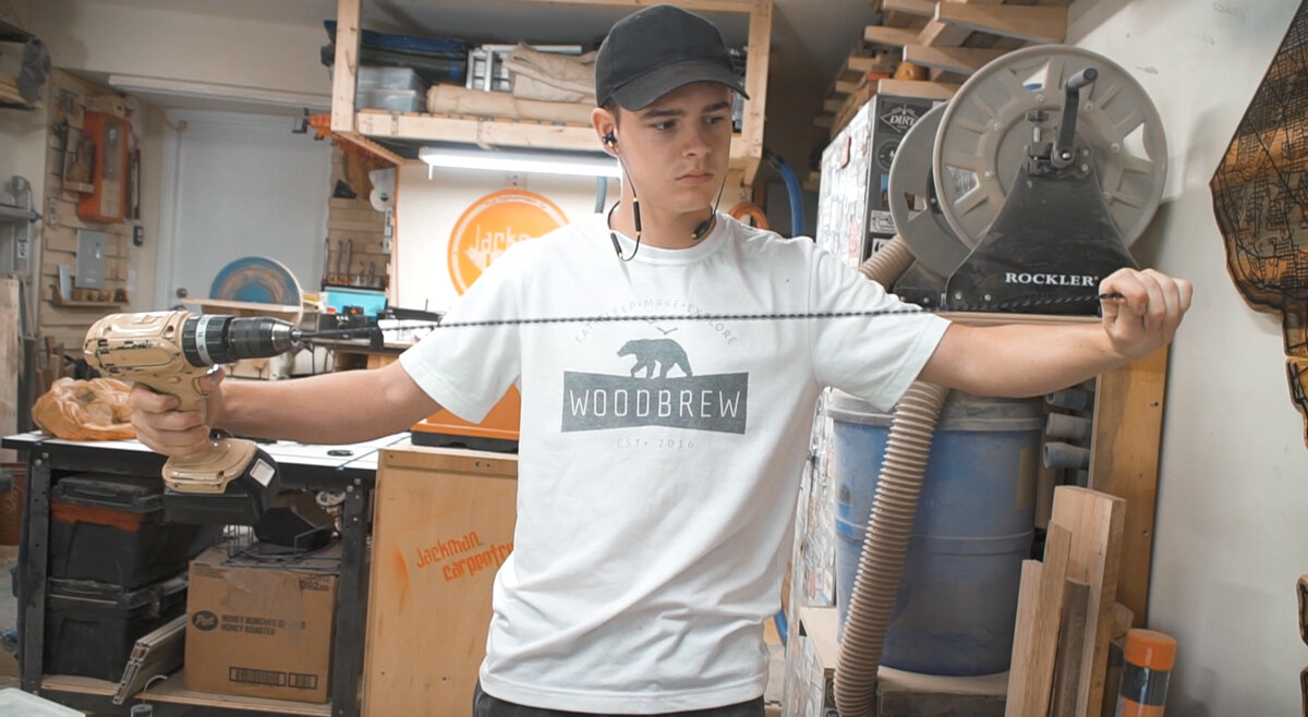
First we are going to pull out a few feet of wire and cut 2 pieces. Using a drill placing the two wiring in the chuck and holding the other ends while we spin the wire to create a nice looking coil of wire. This will really dress up the exposed wire in the finished project.

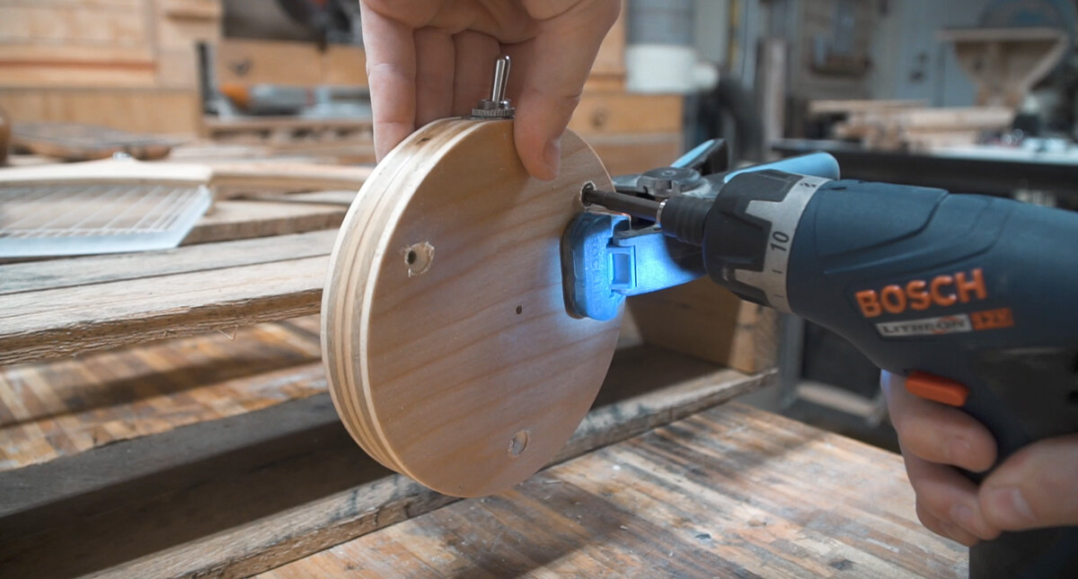
Next we need to drill a hole for that wire to pass through the bottom plate.

After feeding the wire through the hole, Dylan stripped the two ends of the wire to get ready for soldering. Before soldering, we hot glued our power plug (affiliate link) and switch(affiliate link) into the base.

Dylan adds a little solder to the end of the wire to prepare it to be connected to the power plug. Adding solder to the end of the wire and to the terminal on the plug will make the connection easier. The first wire gets soldered to the ground terminal of the power plug.
We added a little hot glue over the connection to keep it in place. Pro tip: Use compressed air to cool the hot glue quickly.
Now solder the other wire to one terminal of the switch.
Cut a small piece of wire and solder it to the positive terminal on the power plug and the other end to the other terminal on the switch. Because we added the small wire between the power and the switch, this makes sure the light only turns on when switched on. If we had connected both wires coming through the base to the power plug, then the light would come on as soon as you plugged it in.

After making sure the two halves of the base would still go together, we moved onto wiring the light section.
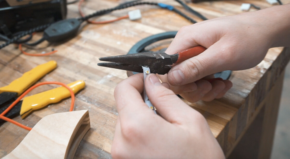
Run the wire through the hole in the top of the light hood, strip and add solder to the ends of the wire. We used an LED light strip that can be cut to any length. The last step in wiring is to solder the positive and ground wires to the LED strip.
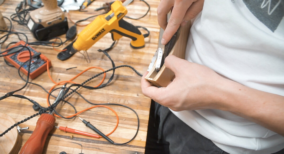
After we pushed the strip into the hood and added hot glue to secure the lights and the acrylic in place.

Last step after we checked and made sure everything worked was to screw the two base halves together.
We are so happy with how this project turned out. Paul also made his own light through the same process and they both look amazing. We also made a video on Paul's channel that was a ton of fun to make. Make sure to go subscribe to him on YouTube so you are notified when that video comes out. Thanks again to Inventables for sponsoring this week's project!